Overview
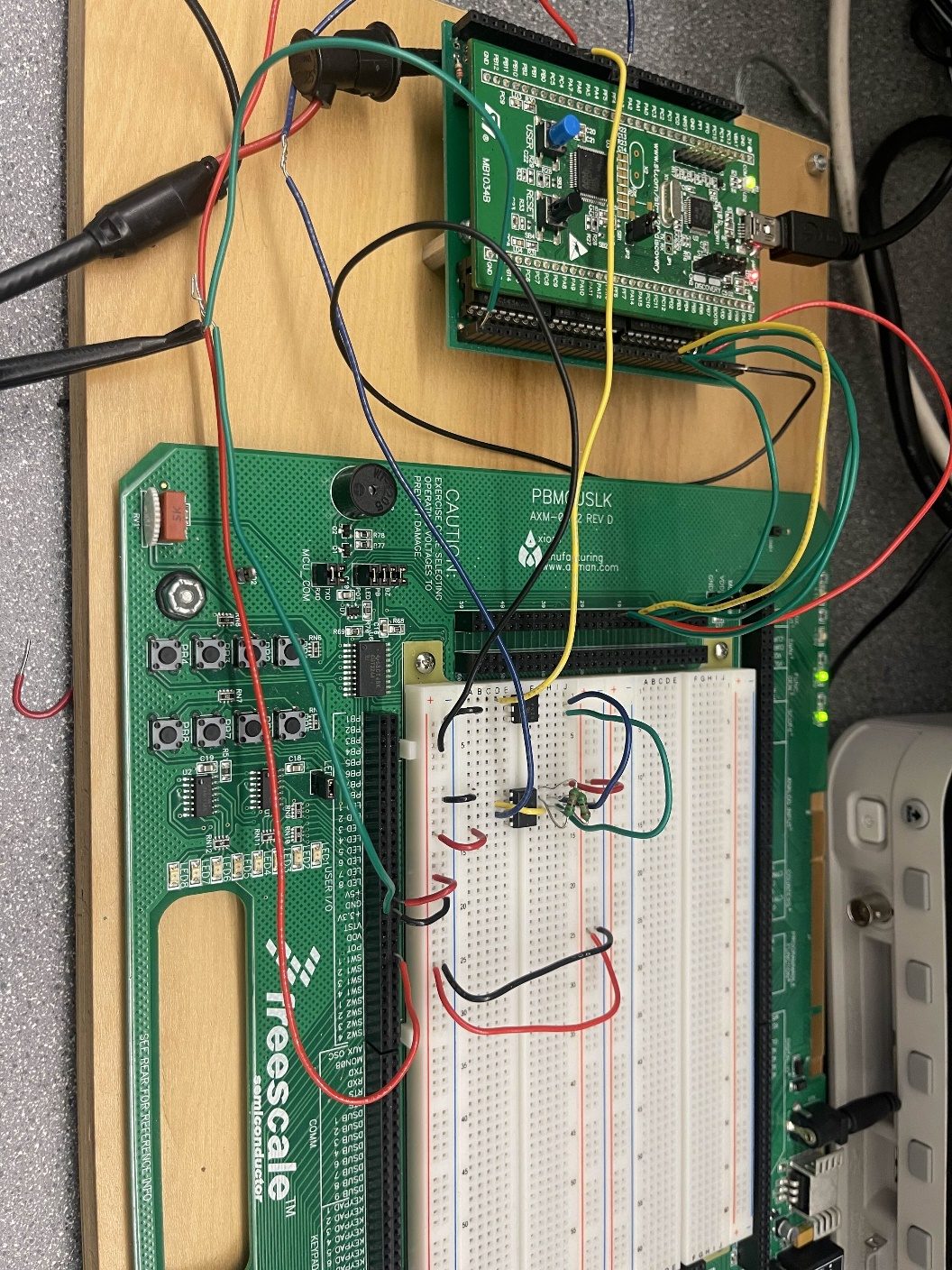
Everything here is register-level C with CMSIS — no HAL. The board's ADC reads a potentiometer, and the DAC drives a 4N35 optocoupler that varies the effective resistance seen by an NE555 astable circuit, changing its output frequency. That PWM signal returns to the MCU, where an EXTI interrupt and a hardware timer measure the period edge-to-edge. A push-button (also on EXTI) switches the measurement source between the 555 circuit and a bench function generator.
Measured frequency and computed potentiometer resistance stream to an SPI OLED display that refreshes in real time. Accuracy was characterized against the bench function generator across the operating range, and edge cases — source disconnection, source switching, hardware reset — were tested explicitly.
Highlights
- Pure CMSIS register programming: TIM, EXTI, ADC, DAC, SPI, and NVIC configuration by hand.
- Interrupt-driven period measurement of an external PWM source, with source switching on a debounced button.
- Analog control path: DAC → 4N35 optocoupler → NE555, closing the loop between firmware and a classic analog timer.
- Live SPI OLED dashboard showing frequency and resistance, verified against lab instruments.